Plotting membrane speakers
Overview
Project for wire plotting of membrane speakers. for wildcard week in mas.836 2018
- Sam Calisch
- Elena Chong
- Zijun Wei
- Victoria Shen
We will use a custom magnet wire plotting tool for the Zund cutter to plot coils for audio speakers.

TODO
waterjet steel layerslaser cut shim layer (500um? 1mm?). (elena)- test heat+vacuum for membrane layers (sam)
verify magnet orientations with gaussmeter.modify coil cutout to extend beyond frame for easy stretching, run job (sam)solder leads (mount RCA jack?) (victoria)test with audio amp
optional
- do a version with 1/16" magnets and 1/16" phenolic layer
- do a couple more iteration and polish final product
Simulation
Two approaches: Coil-magnet, and coil-coil.
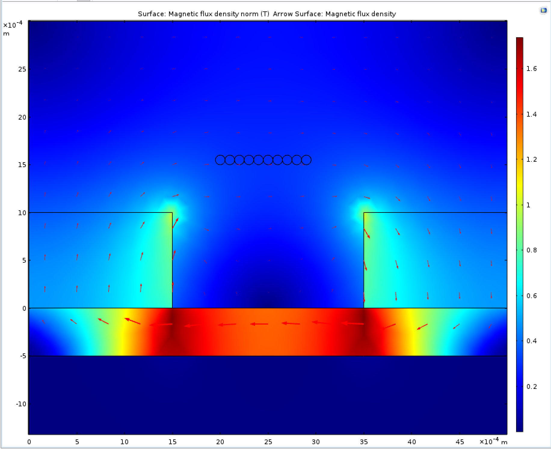
Coil-coil
The coil-coil topology relies on coils to generate all magnetic fields, not just the time varying one.
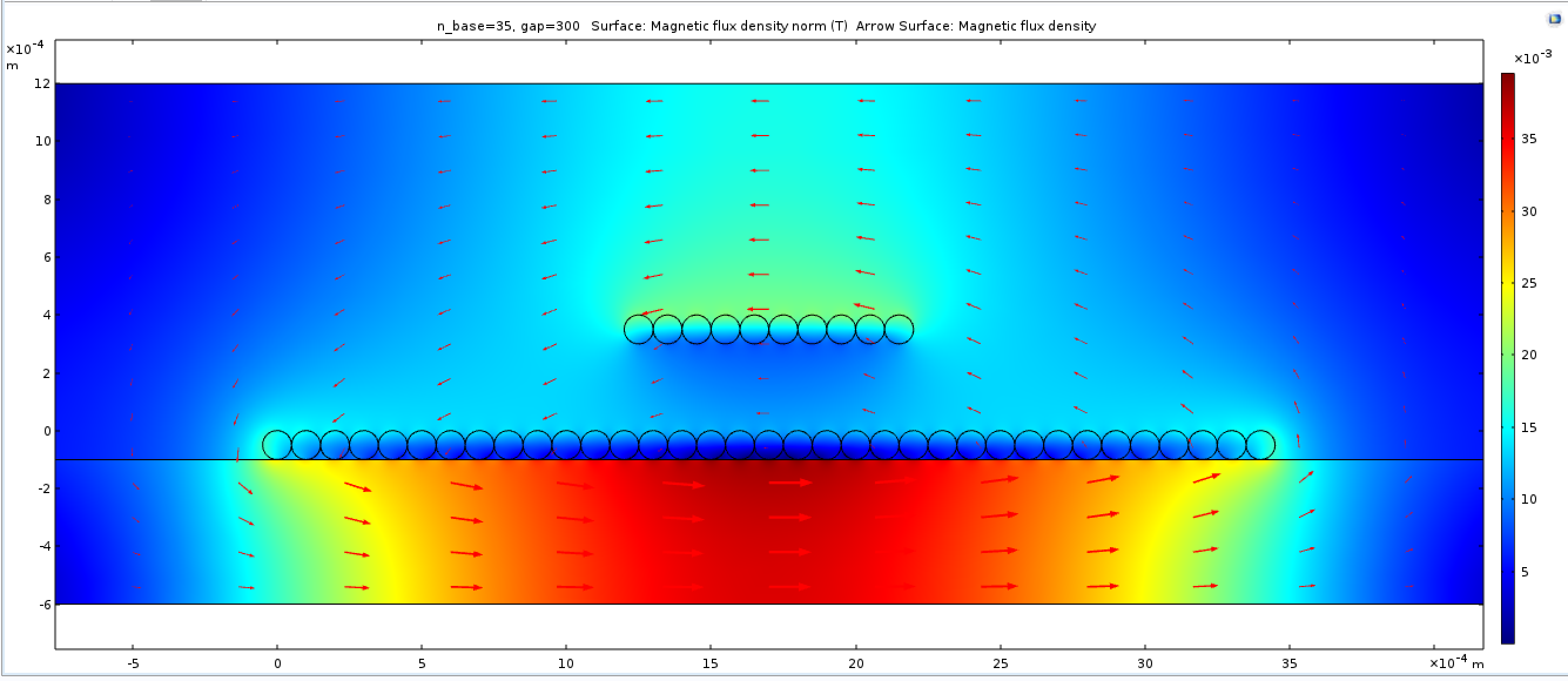
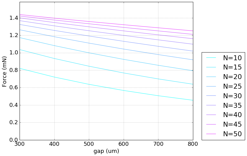
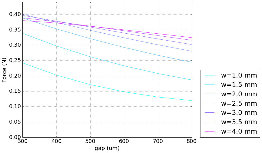
Magnet-coil
The coil-magnet topology (planar magnetic) is used for some high end headphones. It can produce significantly more force than coil-coil, even with very thin magnets.
magnet grids
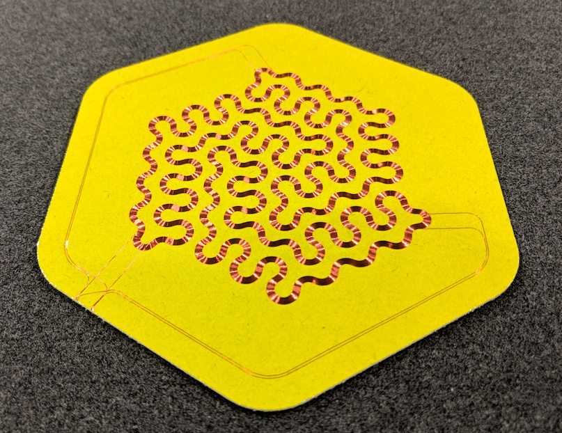
In our meeting this morning, we talked about how rod magnets are more widely available than long, thin bar magnets, and that making grids of rod magnets could make assembly really easy and offer design freedom. Below are two sketches of square and hex grids with coils routed to capture perpendicular flux. Magnets are blue circles, all closest pairs have opposite polarity.
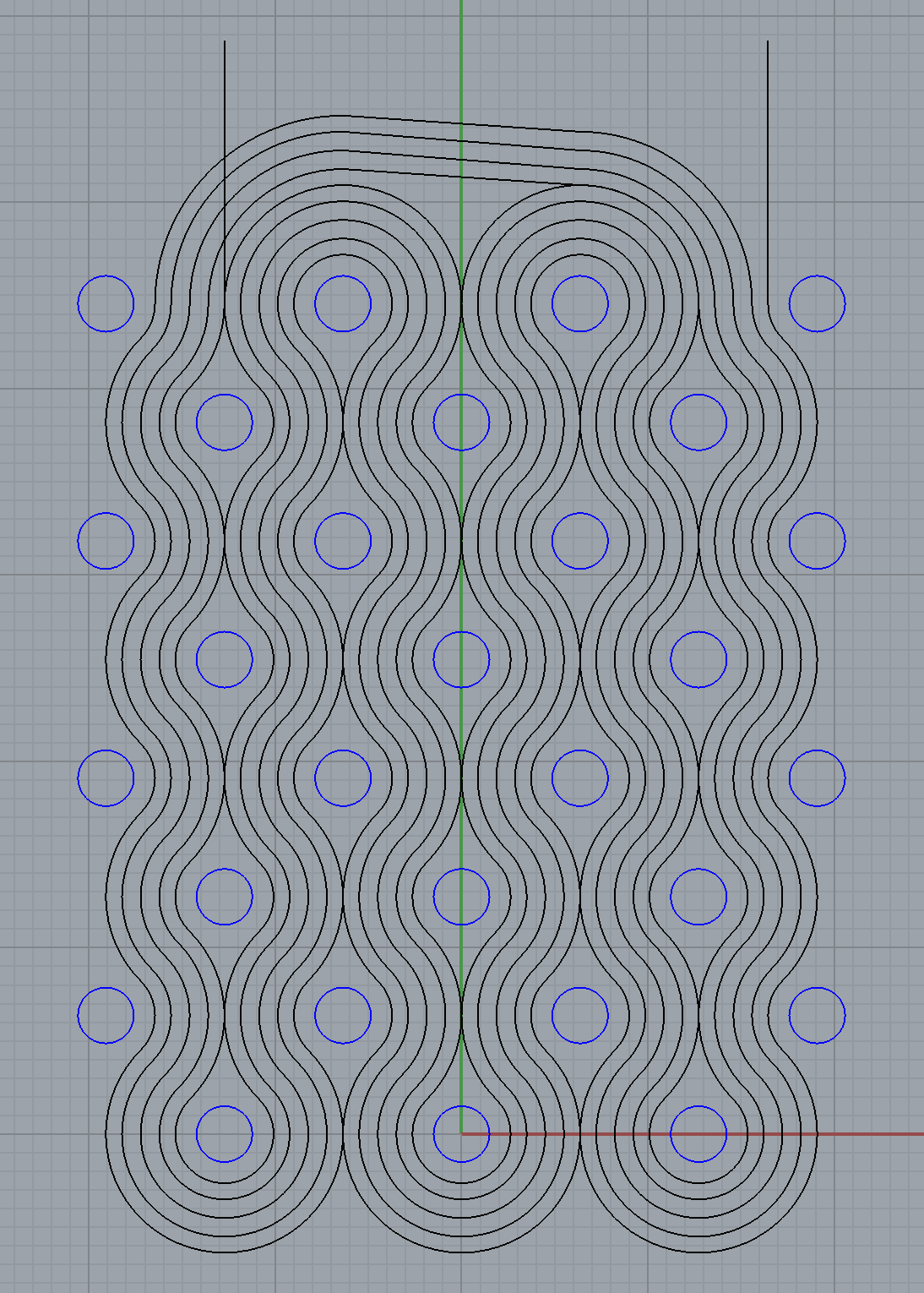
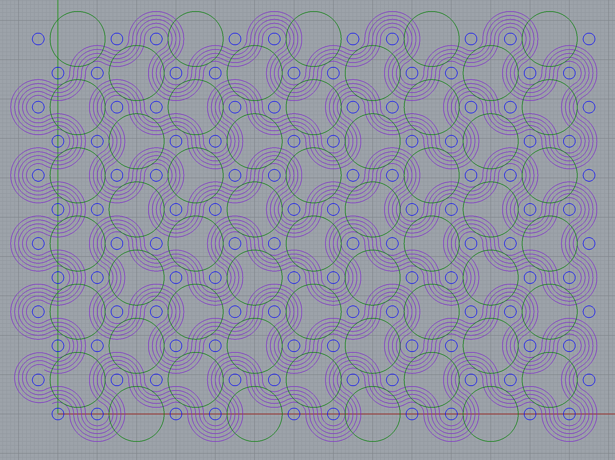
The design below has rotational symmetry, which may help flatten its frequency response.
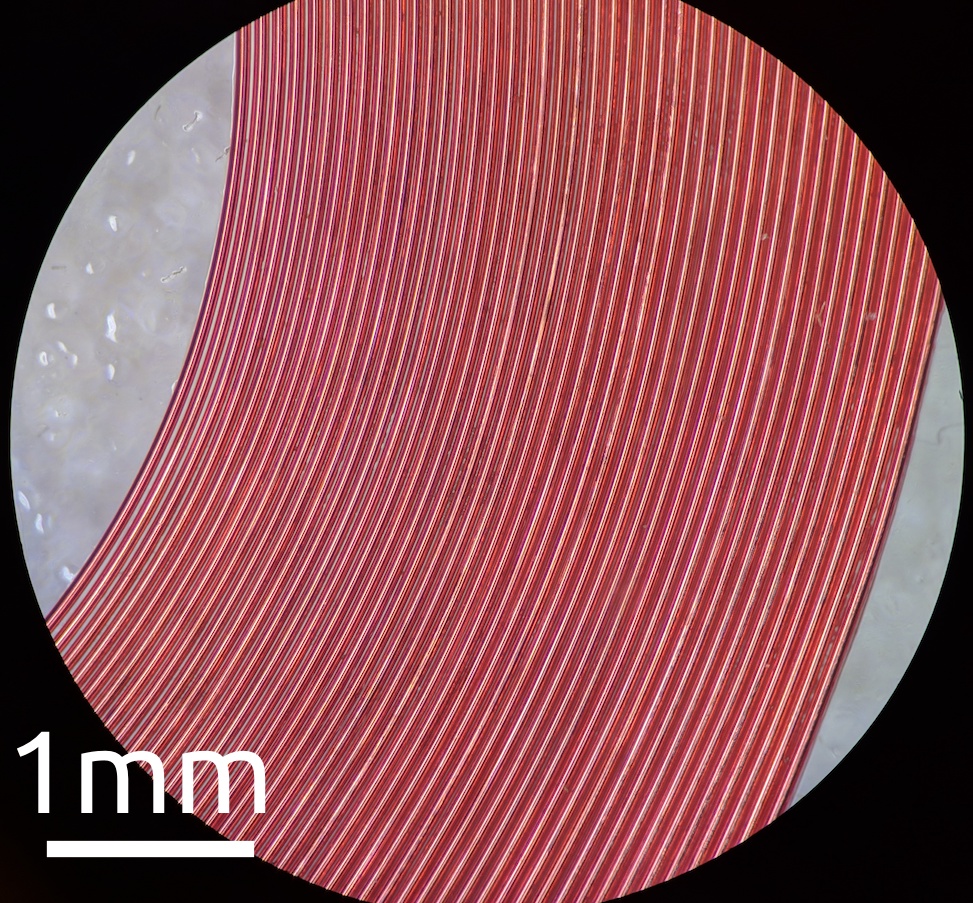
Watching the coils being plotted is fun:
Design and Fabrication
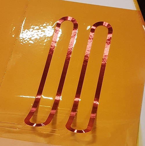
Long coil for testing
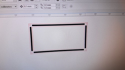
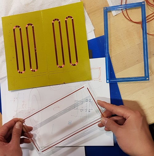
First, we decided to start off with making a rectangular frame for clamping firmly the membrane (wire plotting on 25 micron kapton tape) that Sam initially designed for another project of his.
The initial frame that we designed contained pockets on each side for placing the "rubber" that will create friction between the frame plates.
We used the Epilog Lasercutter to lasercut the frames on 1/8" acrylic sheet.
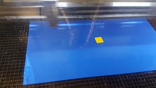
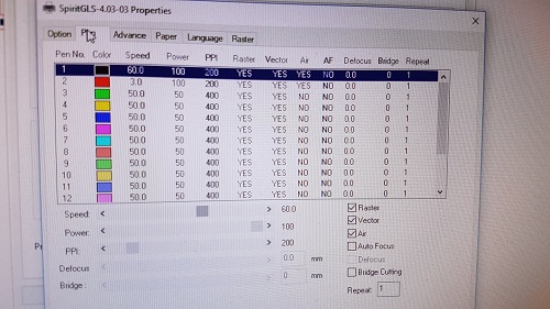
For the pocket, we used 60% speed, 100% power, and 200ppi, for the outline of the frame we used 3% speed, 100% power, and 200ppi.
One of the resulting frame looked like the picture below:
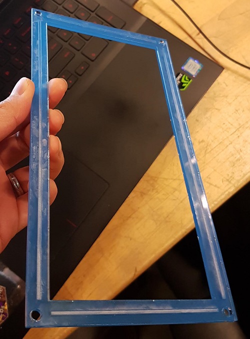
We used Crazy Glue to glue the rubber in place.
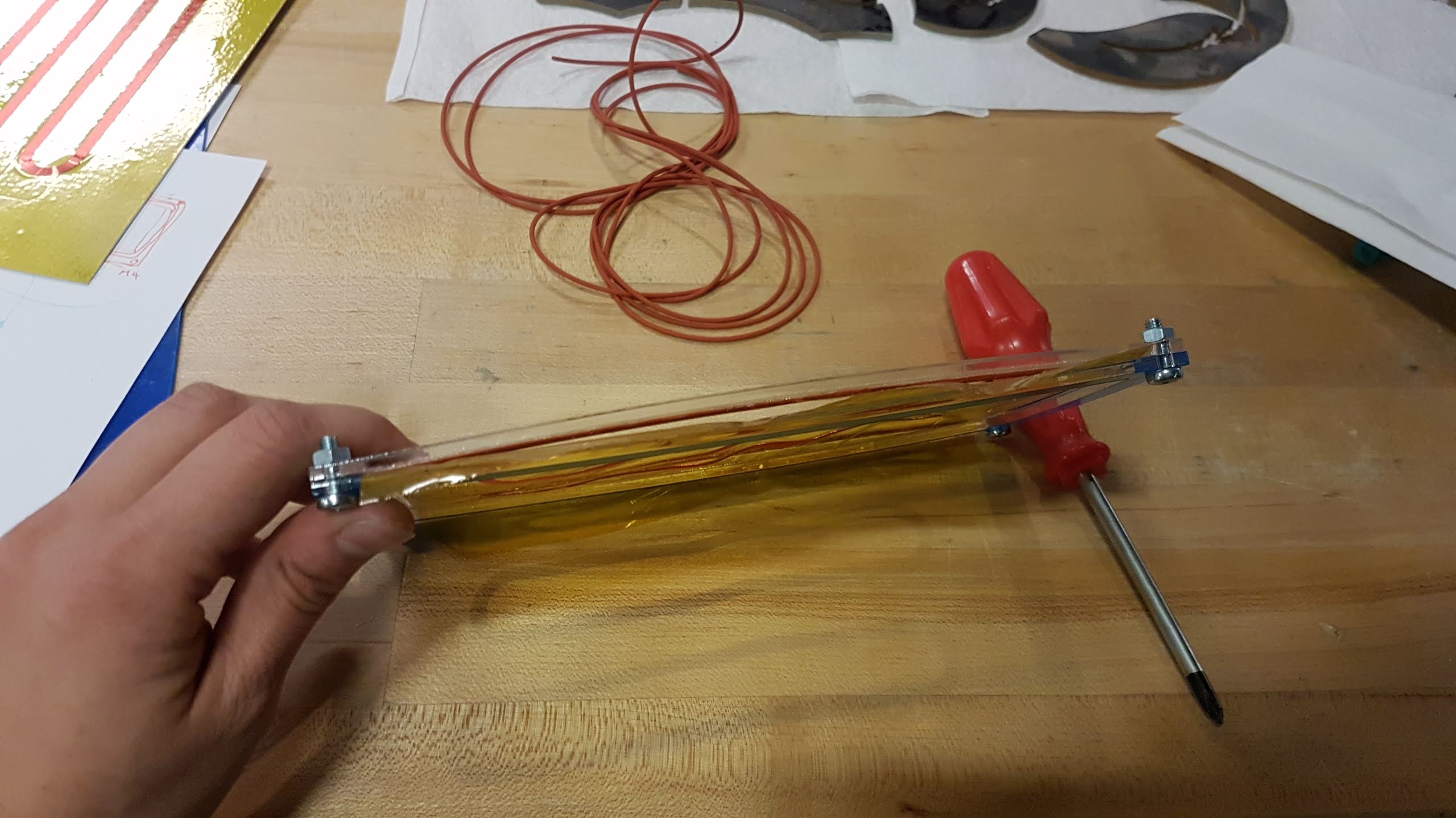
For the first attempt, we just placed the membrane between the two plates and used a few M4 screws to clamp it.
We noticed that the acrylic is not a good material for exerting pressure. It started bending, which defied its purpose.
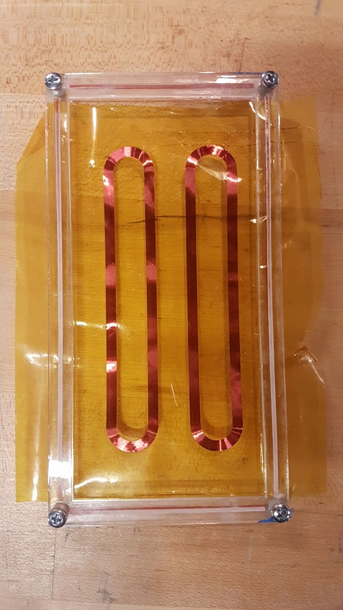
A bird view of membrane clamped with the long rectangular frame.
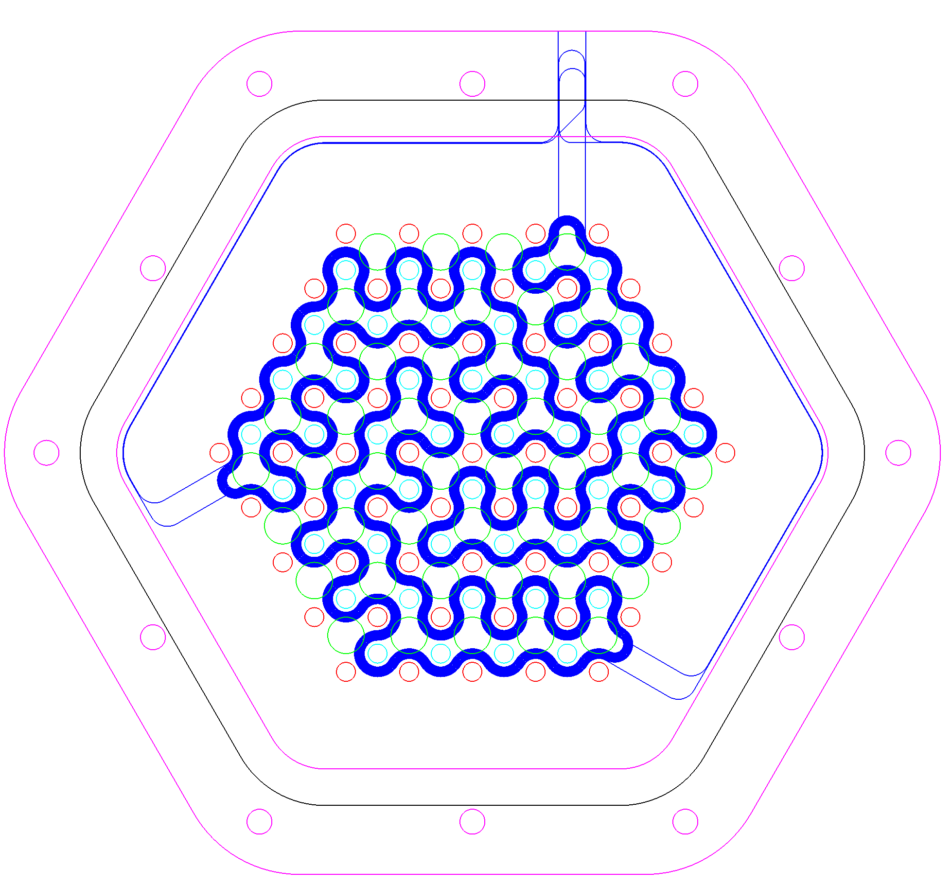
Magnet-Coil Hexagonal design
After brainstorming for the first design iteration, we decided on using magnet and coil with Sam's idea of a magnet grid. He succesfully got a few plotted out nicely on 25 micron kapton tape.
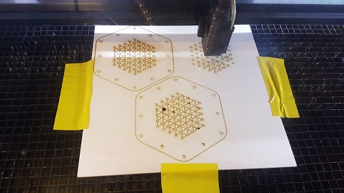
We then lasercutted the outer frame from 1/8" wood to clamp the coil membrane.
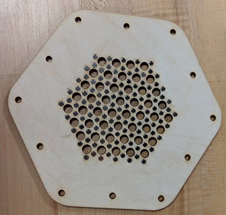
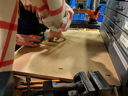
We then lasercutted the magnet grid plate from the same kind of wood.
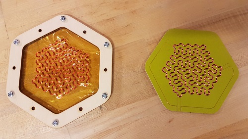
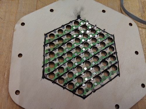
Then, 1/8" magnets were placed in the holes from the magnet-grid plate. Each grid has the opposite polarity.
We used a Gaussmeter to check for the magnets polarity.
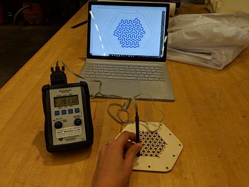
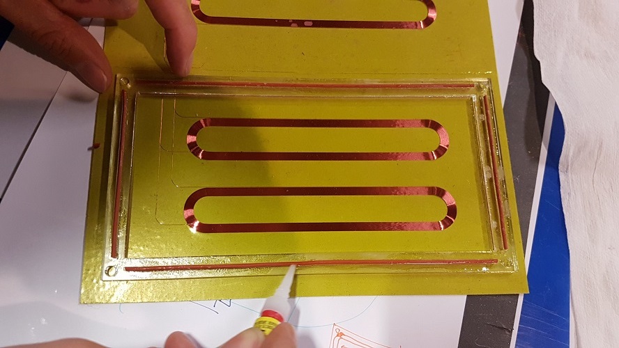
Here is the mapped out magnet-grid. Green for positive and black for negative polarity. We later spray painted this plate with yellow paint to cover the drawing.
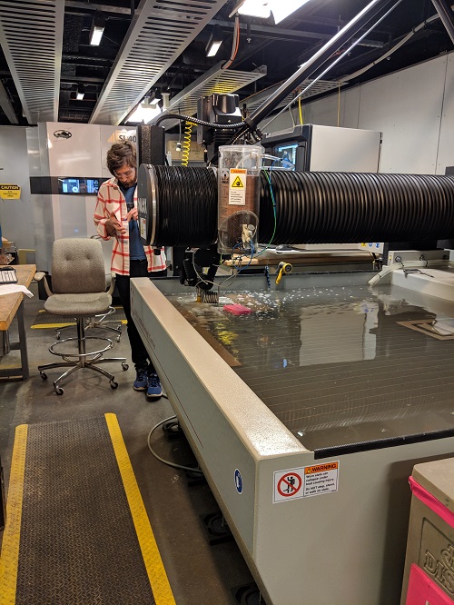
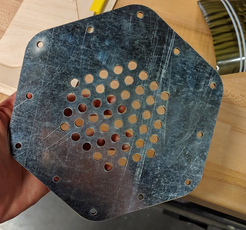
Sam used the water-jet to cut out a steel plate for the ground plate (the base).
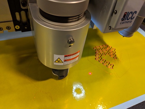
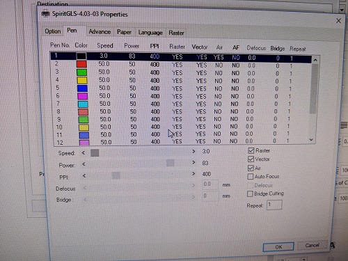
We tried to lasercut some of the materials that Sam provided us. We tried to cut the 1/8" and 1/16" phenolic sheets with the lasercutter using 0.7% speed, 100% power, 400ppi and were not successful, so we decided to just do it on the plastic sheet.
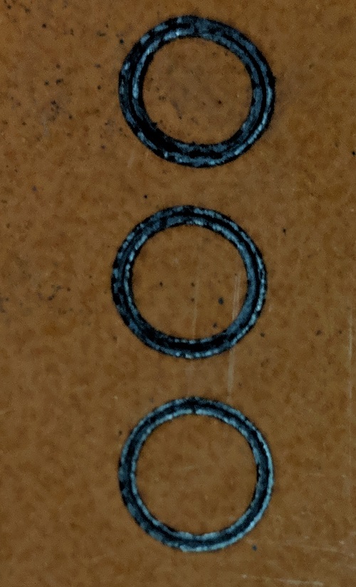
It did not even go through the sheet! Here is a picture of the burned phenolic sheet at different speed level (0.7-1.5%).
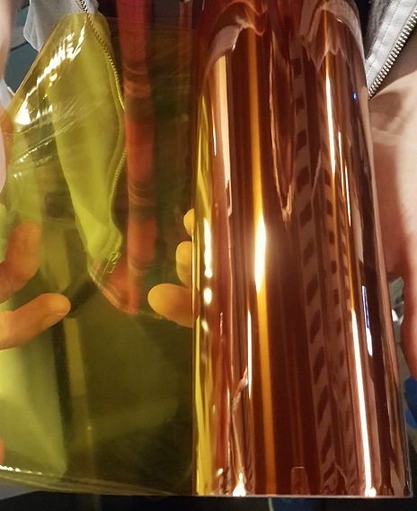
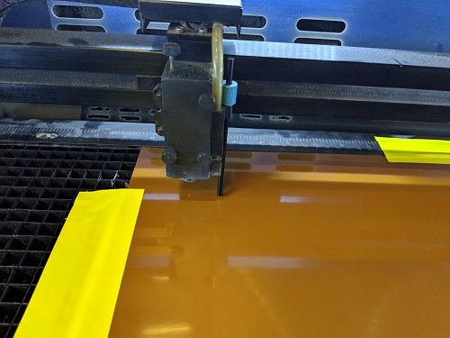
Sam also provided us with a very thin plastic sheet.
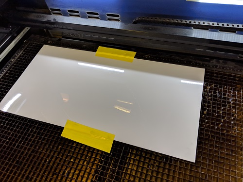
We tested the cutting settings and found that the best values were: 3% speed, 80-85% power, 400 ppi.
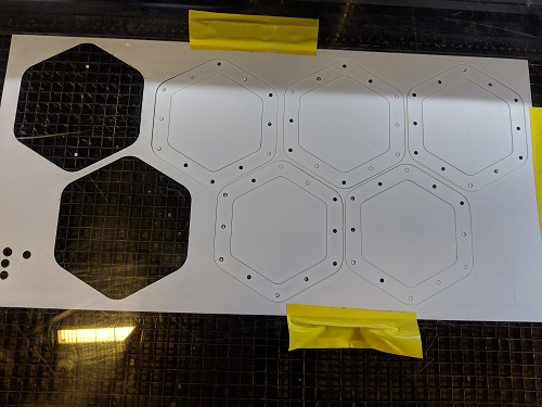
Here are some five shim/spacers we lasercutted from this thin plastic sheet.
During our design discussing, we did not get that far ahead into thinking about the testing process. We forgot to add clearance for an RCA plug which will be used for sending audio signals to the coil. Hence, we had to separate the magnet-grid plate from the steel plate (We snapped them together beforehand.)
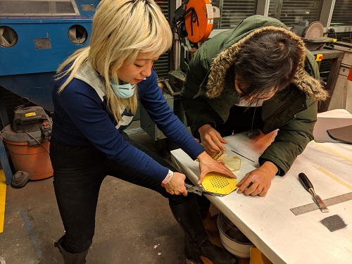
We used the drill to create a bigger hole for the RCA plug. Had to do it for all layers: steel plate, magnet-grid plate, spacers/shims, frame plate.
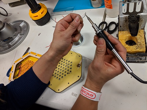
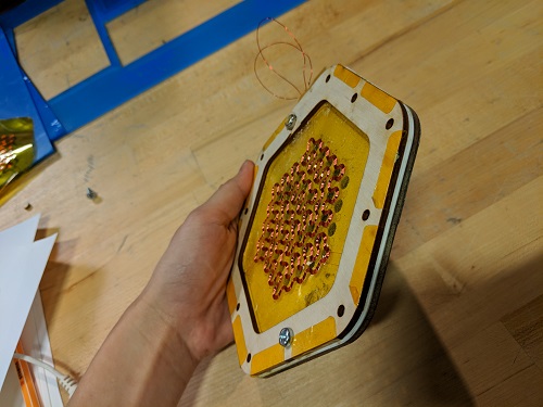
Some fine soldering work came next. Had to peel off the insulation layer from the copper wire for soldering. The copper used for plotting was 40 gauge which makes it difficult to connect to the RCA plug. Thus, we stepped up the copper wire by soldering it to a thicker one.
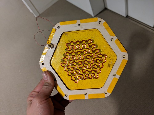
The resulting planar speaker.
Testing
It is testing time!
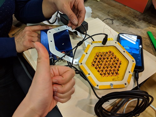
We tested our first iteration and here are the results:
No spacer/shim. Minimum separation between the coil membrane and the magnets plate. (First Reaction!)
With two spacers separation between the coil membrane and the magnets plate.
Three spacers separation between the coil membrane and the magnets plate. This video also shows some of the layers of this planar speaker.
First iteration was a success!