Wire plotting membrane speakers
Overview
This project is to make planar speakers by plotting fine magnet wire on a membrane, instead of the usual voice-coil and cone construction. The resulting speakers will be low profile, low mass, and (hopefully) high performance. It's my hope that by reducing the relevant design degrees of freedom (the path of the coils, the arrangement of permanent magnets) we can design the geometry and actuation of sound systems as a whole, rather than as assemblages of individually optimized components.
Wilcard week and first prototypes
This project started during wildcard week of How to make almost anything, MAS863.18. Work from that week is documented here.
We simulated several arrangements to drive a membrane for a speaker. Coil-coil intereractions are nice because they don't require permanent magnets, but the force produced in our geometry is very small (~1000x smaller) compared to that of coil-magnet interactions.
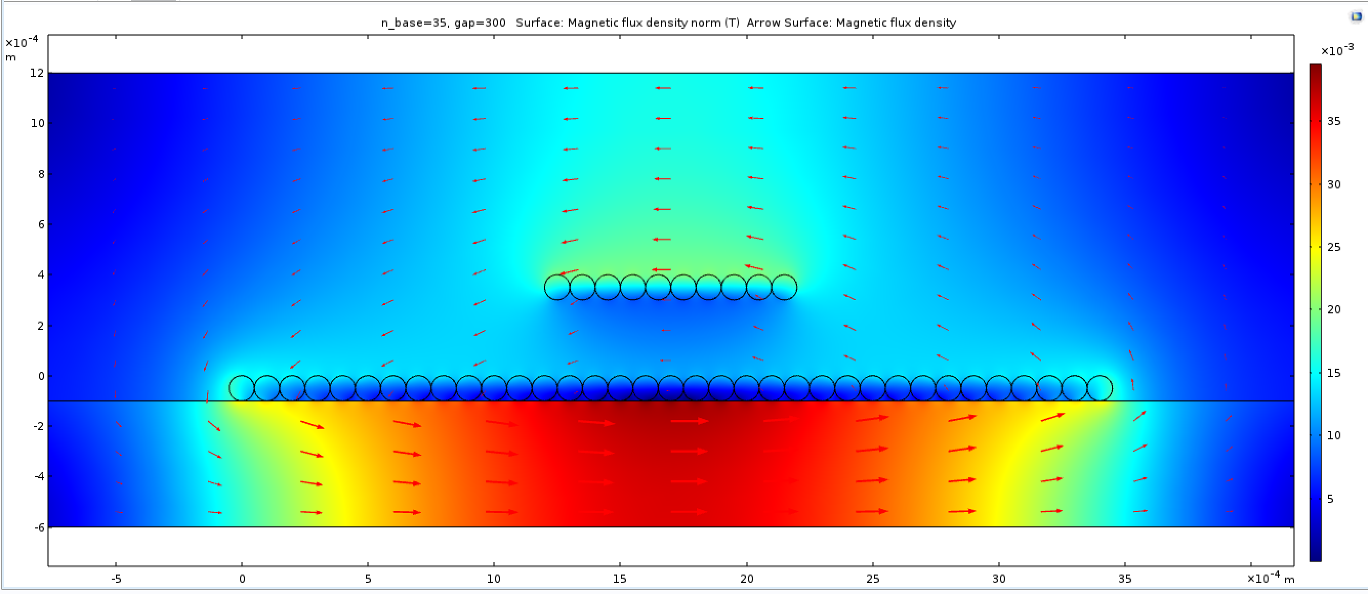
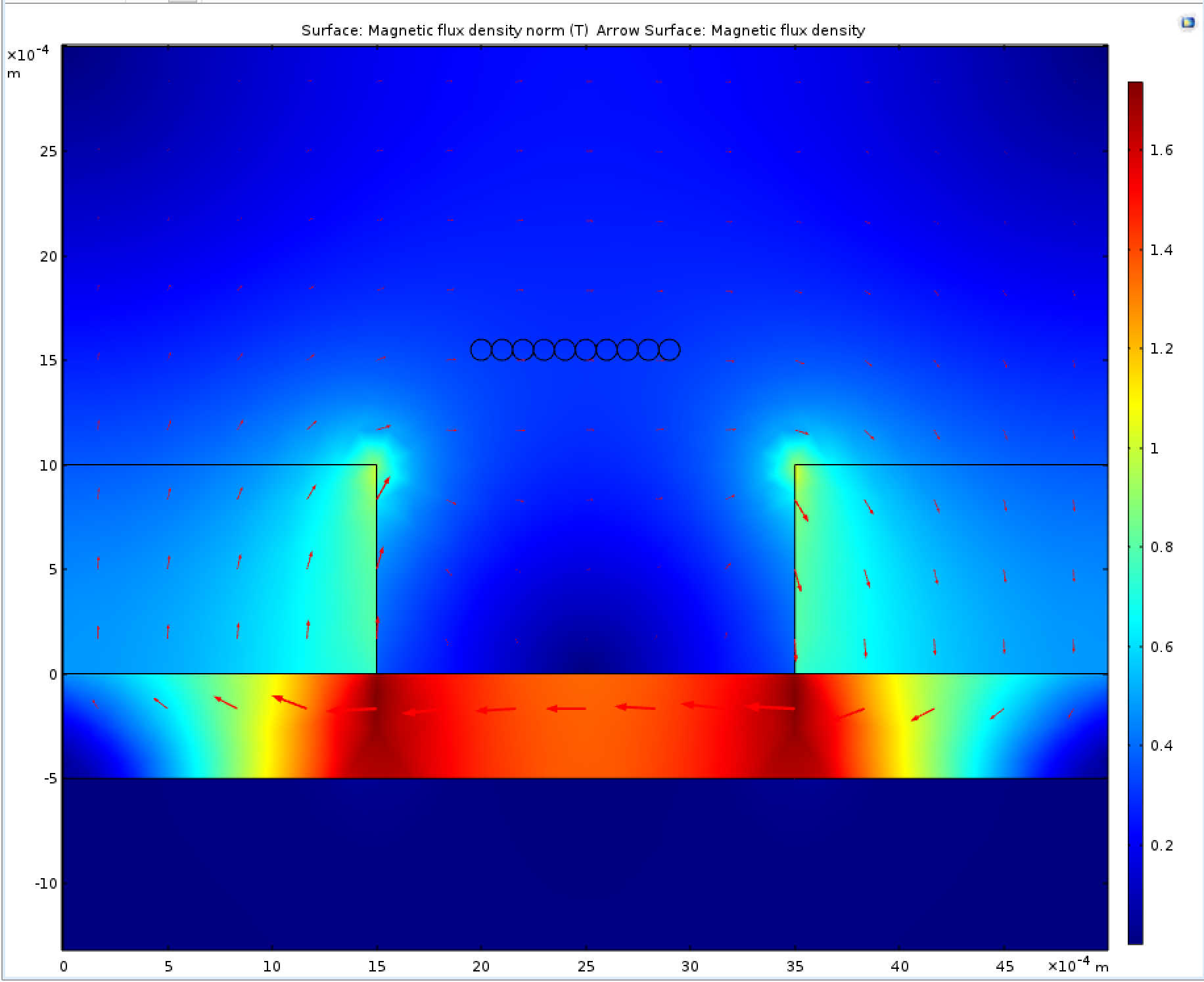
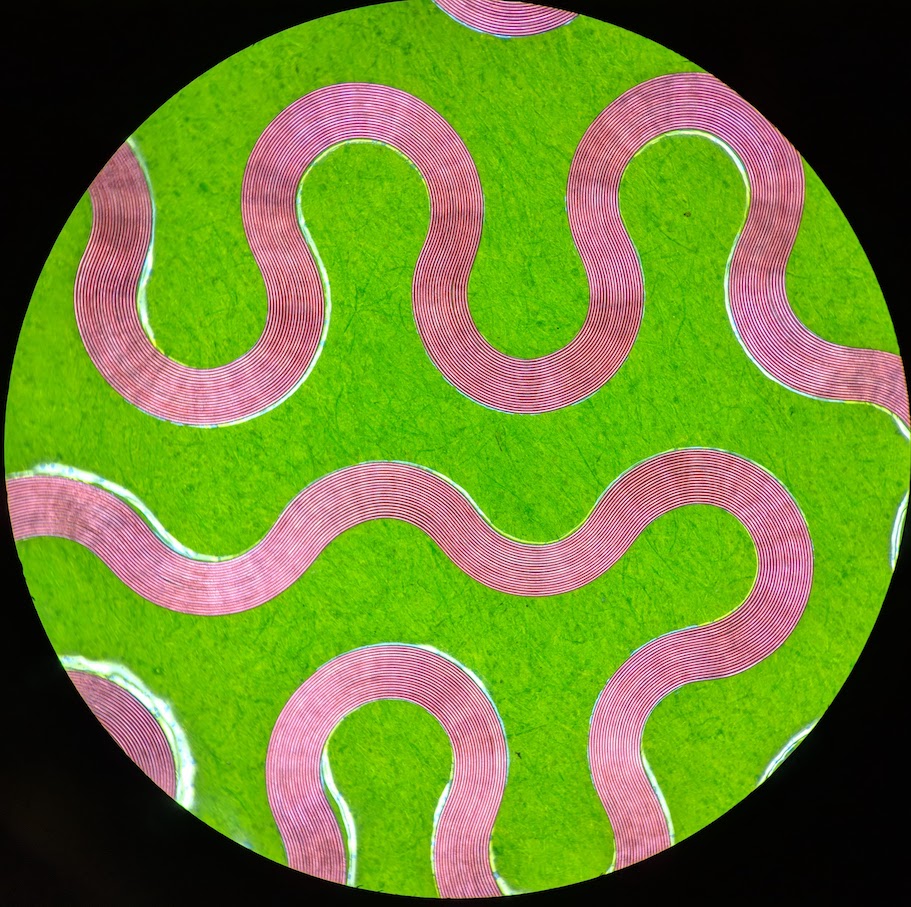
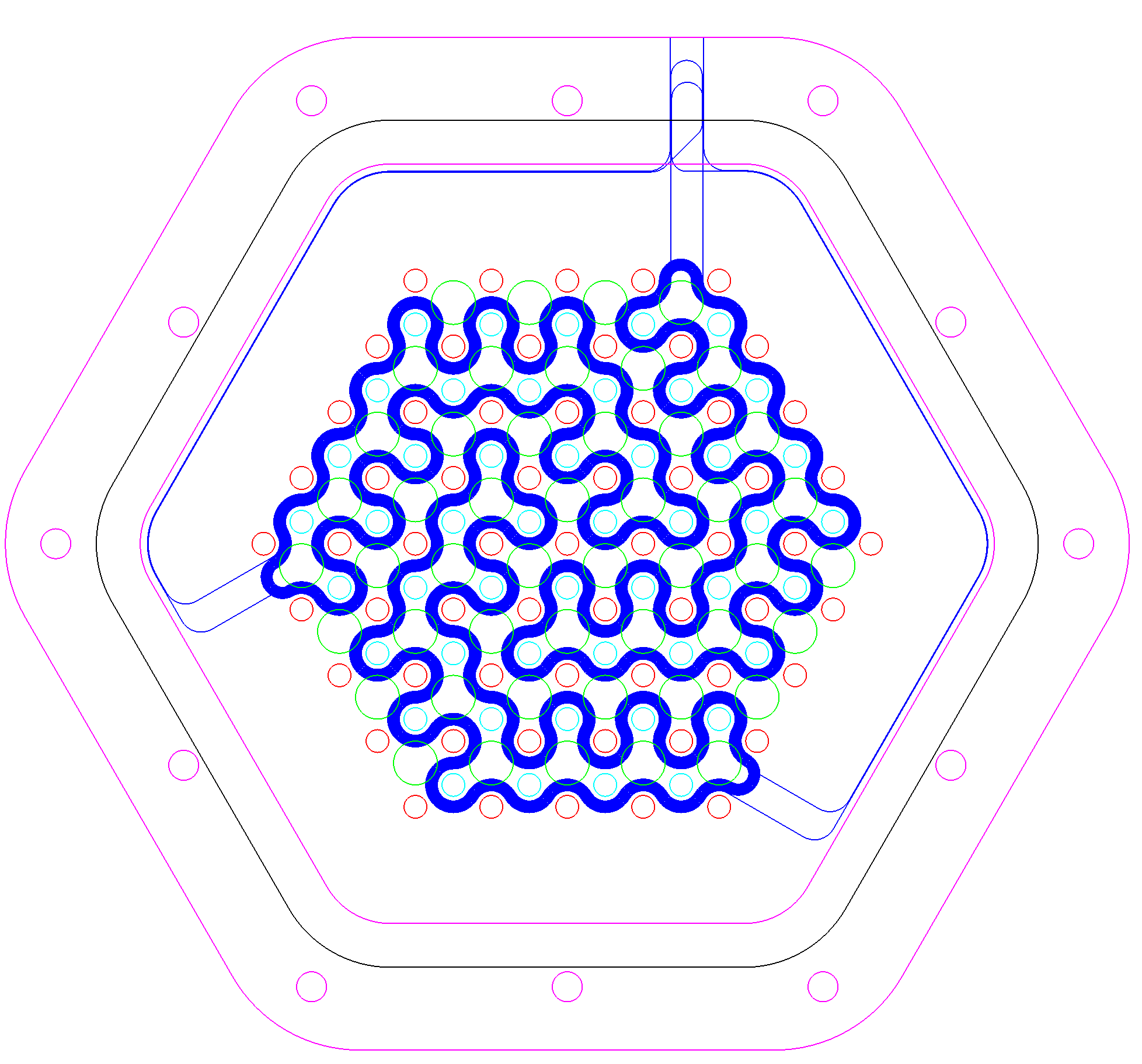
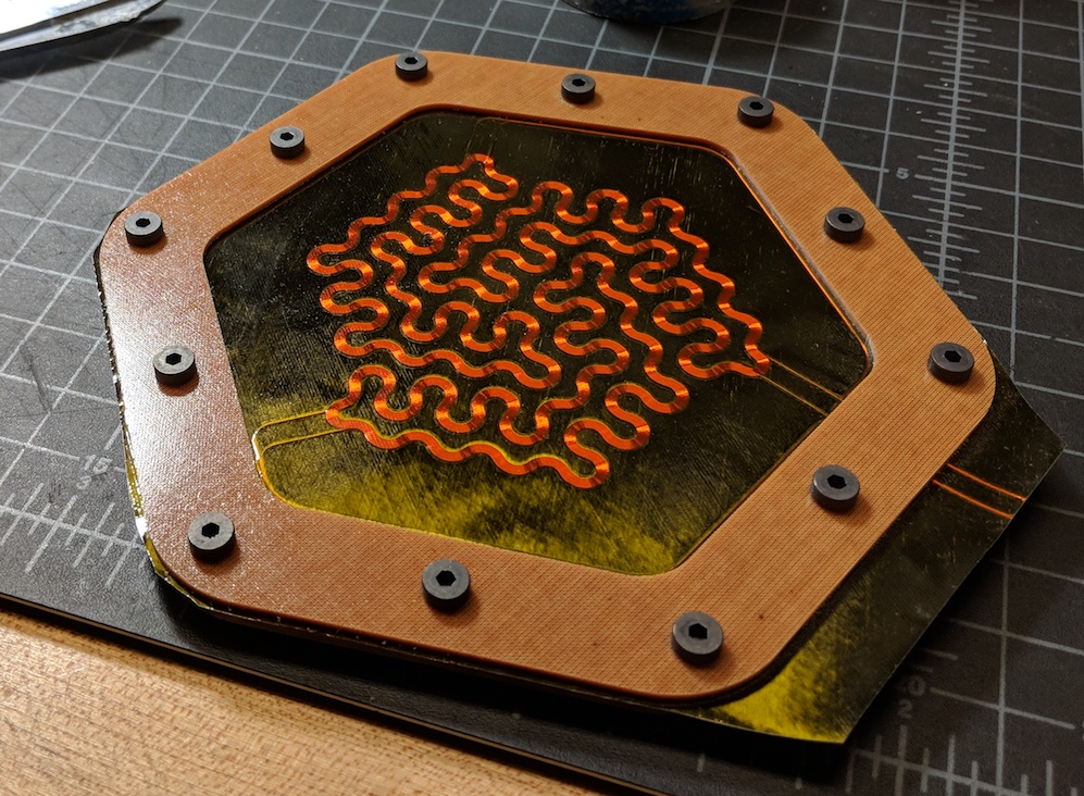
Given this, we decided to use arrays of neodymium disc magnets, which are cheap and easily available in a variety of dimensions. Planar magnetic speakers often use flat bar magnets, but these are more expensive and difficult to arrange on the substrate. The design challenge is to route copper coils to perpendicularly cut the line segments between all adjacent magnets, while minimizing the additional run (wasted copper) and maintain symmetry of the membrane (so the deformation modes aren't deformed). Below is a design with three-fold symmetry that can be extended to an abritrary radius by extending the spiraling pattern.
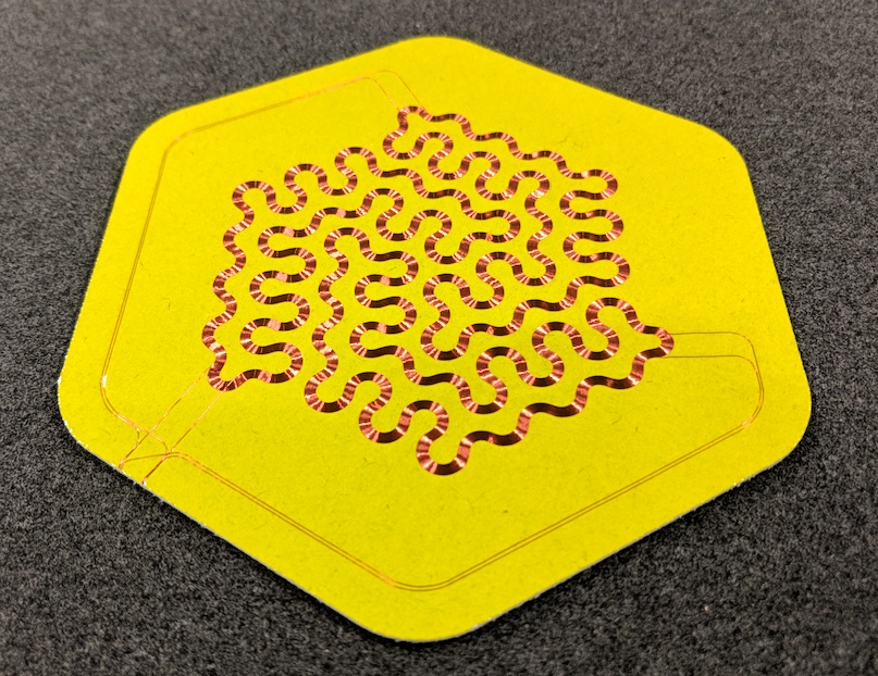
Below is plotting of this pattern onto 1 mil kapton tape.
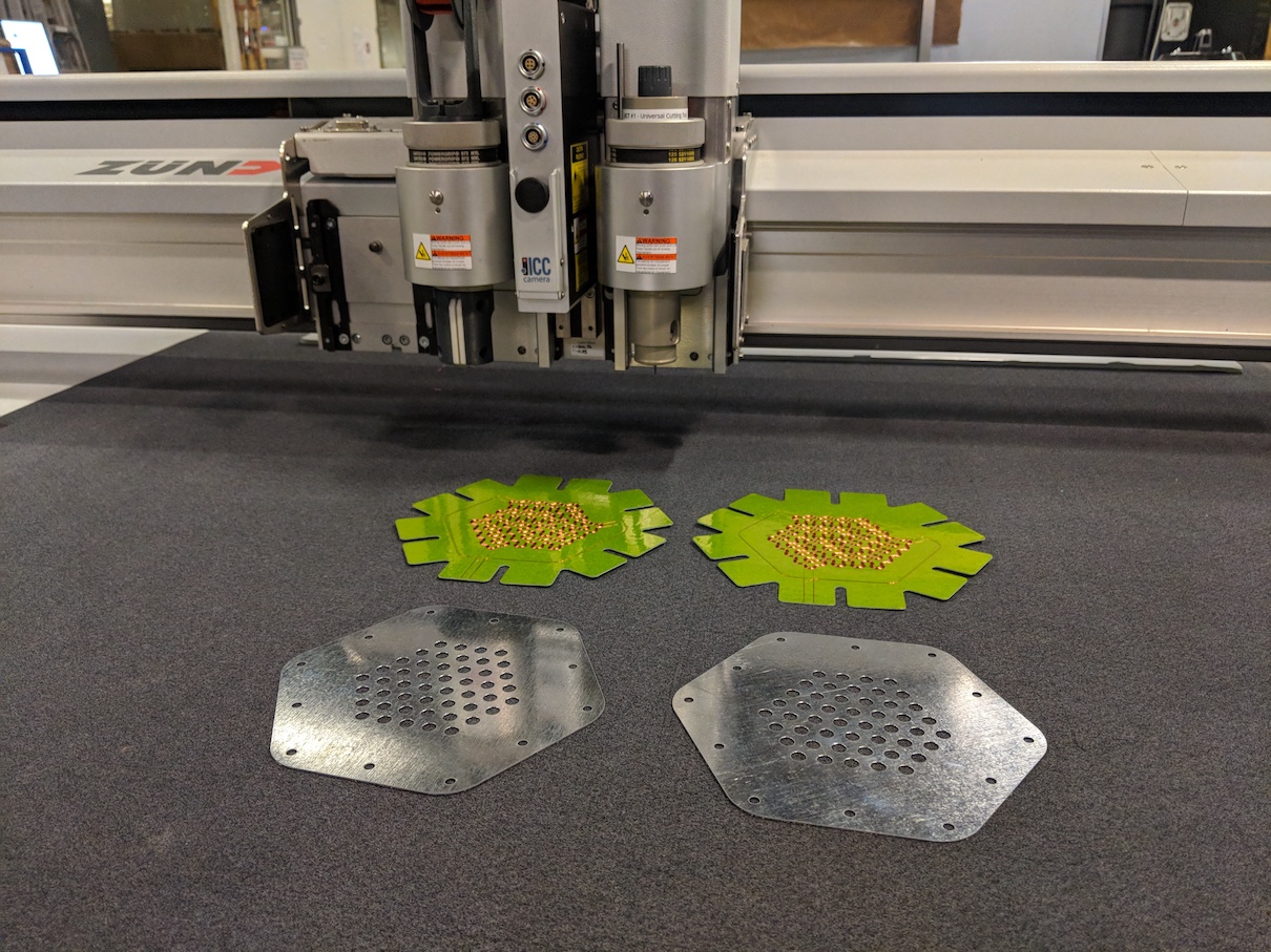
Two membranes and the .015" backiron plates:
First test:
Stereo:
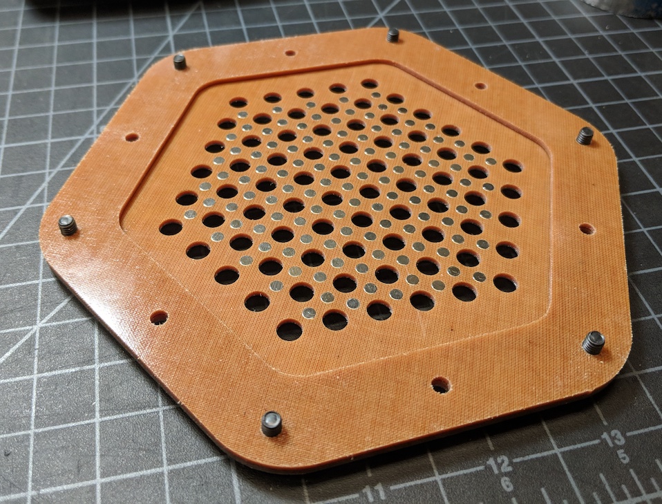
I did some more prototyping on this design, using milled 1/16" cotton-phenolic, instead of laser-cut 1/8" plywood. I also cured the membrane onto a thin sheet of carbon with a 0,+60,-60 layup. I also switched to 1/8" (D) x 1/16" (H) magnets, instead of 1/8" (D) x 1/8" (H), because the simulations predicted the force output would be similar.
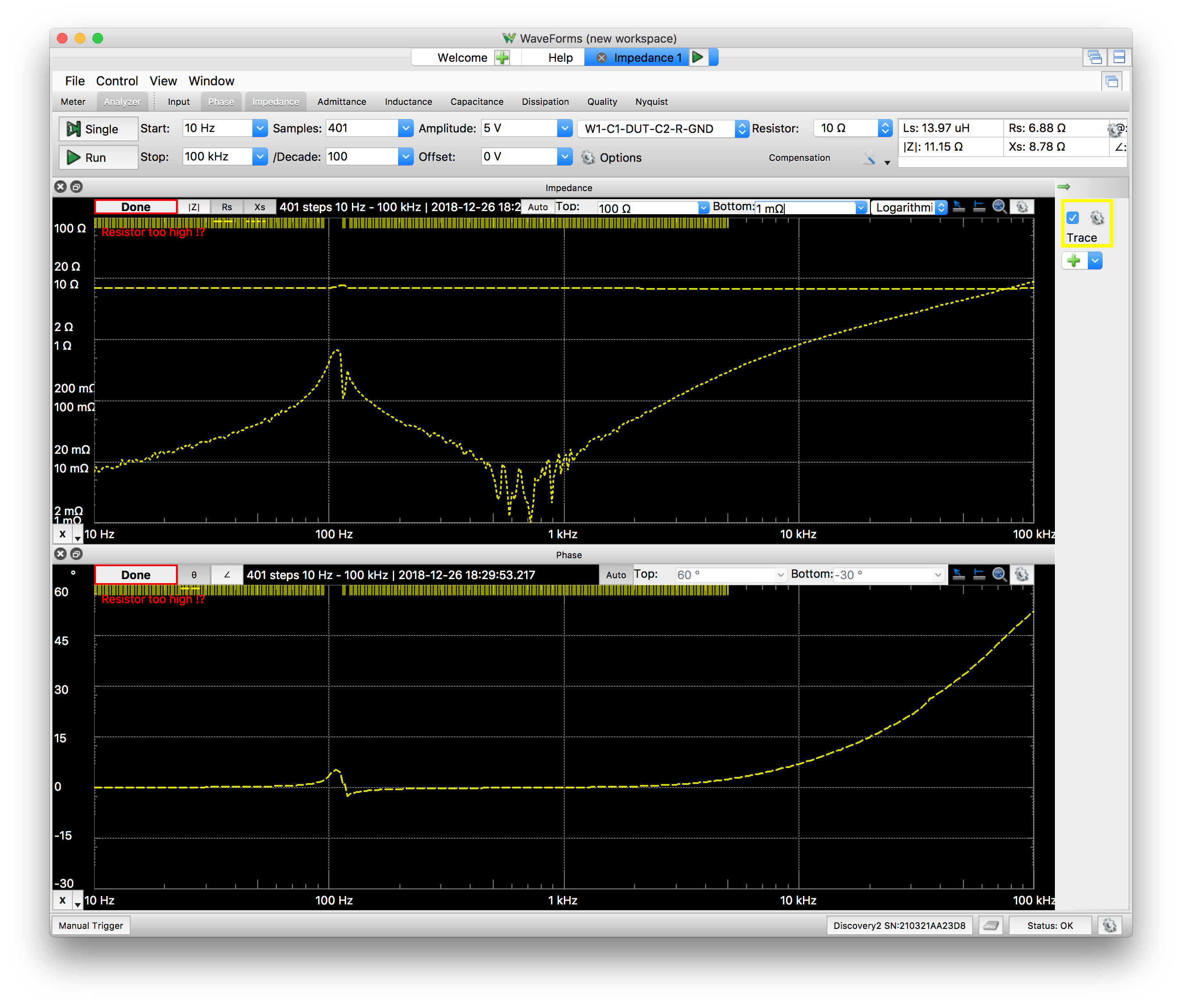
The DC resistance of these speakers came out to 7.5 ohms -- not too far off the 8 ohms I was shooting for. I also analyzed the impedance as a function of frequency (using the handy Analog Discover 2 USB oscilloscope), shown below. We can see the fundamental resonance a bit above 100 Hz (note: next prototype should make this lower).
I took some high speed video to look at the deformation modes. The fundamental mode is, well, fundamental:
I also used the IR imager to look at the heat distribution when driving the speaker hard:

Coil layer improvements
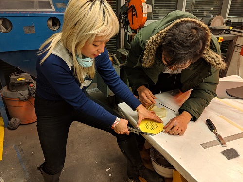
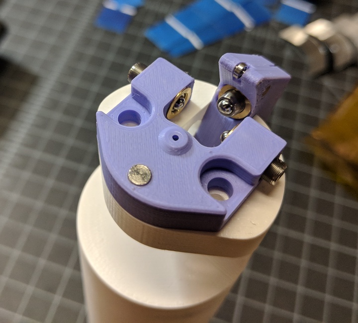
The pattern for this speaker stressed my coil laying tool in ways that my previous prototypes hadn't, and the the applicator tip became a point of failure. I'm working on two improvements to this. First, the software correction for tool offset from rotational axis has been a pain to keep calibrated and is a source of error when pushing the limits of radius of curvature. To get around this, I designed a mechanical correction in two axes for the tool center point using 3/16-100 microadjustment screws. By using these adjustments and measuring the output with my zund microscope tool, I can dial in the alignment to about 10 microns.
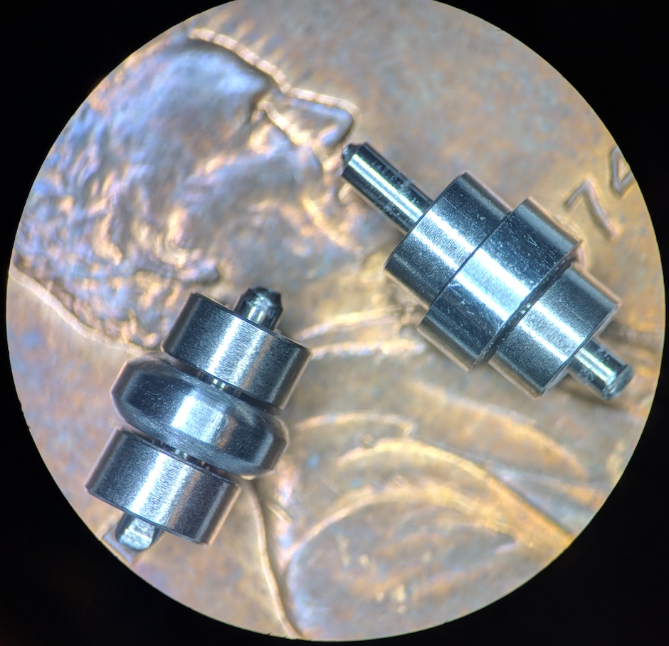
Second, the winding paths of this speaker membrane put torque and axial load on the single 3mm OD ball bearing (with 1mm balls inside!) that I had been using to apply the wire. After a few jobs, this roller would have the characteristic "crunch" of an overloaded bearing. I owe an offering to St. Venant. To fix this, I made a small roller applicator, held by two 3mm OD bearings. This effectively limits the torque seen by the bearings and doubles the effective radial load (because there are two instead of one). It also allows me to experiment with different applicator profile shapes. Two are shown above, on a penny for scale.
The two bearings definitely held up better than the single bearing, but I still managed to overload them eventually. This leads me to think that failure mode is a result of either contamination in the unsealed bearings, or significant axial force during plotting. I think both might be solved by switching to a plain bearing instead of a ball bearing. Plain bearings can be made to be much more compact and to take much more force than ball bearings. The trade-off is generally a higher coefficient of friction as compared to properly working ball bearings. I'm going to make a plain bearing version of the applicator (either with porous oil-embedded SAE 841 bronze, or simply with a lubricated brass bearing) to see if the friction is at an acceptable level for plotting the wire.