Use Fab Design Rules in Eagle
This will help you make sure that traces are not too close together!
In this folder, find fabcity-designrules.dru
In Eagle, in the Board Window, find edit >> design rules
On the first tab, use 'load' and load this .dru file.
Now you can use the 'DRC' command to check!
Automate the generation of trace.png and cutout.png files
Matt Keeter wrote a Python script that opens up Eagle and exports a number of pngs using ImageMagick.
To get this script to run, use the following steps:
- Save eagle_png.py into the folder where you keep your Eagle project folders containing .brd and .sch files
- Install ImageMagick
- Create a polygon over your .brd design on the Milling layer (number 46)
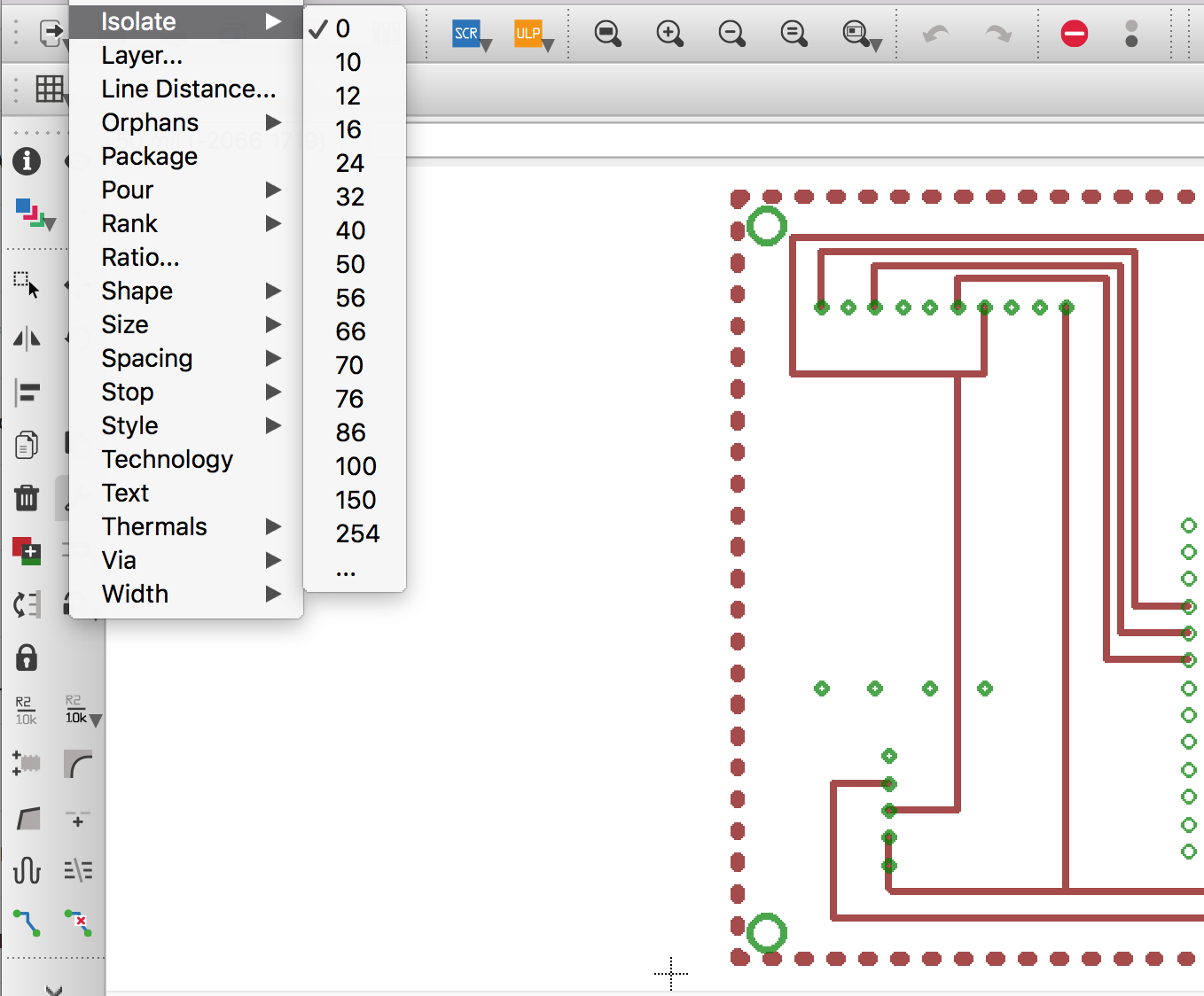
- Set the isolate value for the polygon to a number greater than 16, this will ensure there's enough black space for mods to generate toolpaths in (see image below)
- Save your .brd file and close Eagle
- Run eagle_png using the following command
python eagle_png.py board_folder/board_name.brd - The script should have saved several .png files into the folder where the .brd file is
Note: With later versions of Eagle (9.0.1+), by default it is configured to show text similar to "1-16" ontop of each via. This comes through even when exporting your final image. To remove this artifact, type the following in the commandline:
SET Option.ViaLength 0