UrumbotXY 2.0

This project aims to push the limits of easy-to-replicate, high performance cable driven motion. This coreXY motion platform uses a nylon-coated steel cable under high tension to transmit fast and precise motion.
Fabrication
This design uses a mix of flat parts, and 3D printed parts.
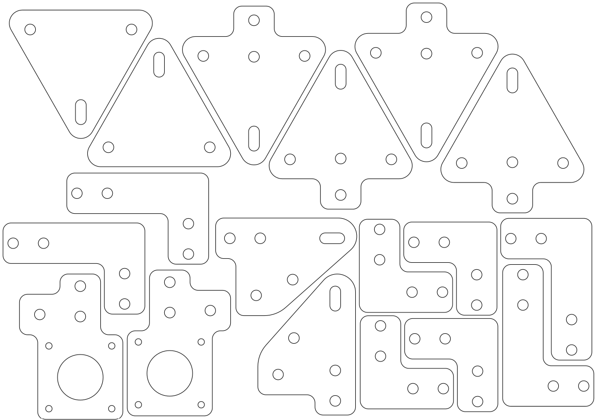
The flat parts can be laser cut or waterjet out of a material 3-5mm thick. A file containing all the parts can be found here, and fits on an A4 page:
The files to 3D print can be found here, and fit on a standard Prusa bed. The recommended material for the print is PETG, though PLA can be used if no other option is available. The main issue with PLA is that is will creep overtime, offering no long term guarantees on a mechanical part.

Once the files are ready, gather all the hardware you'll need and follow the assembly steps below.
Assembly
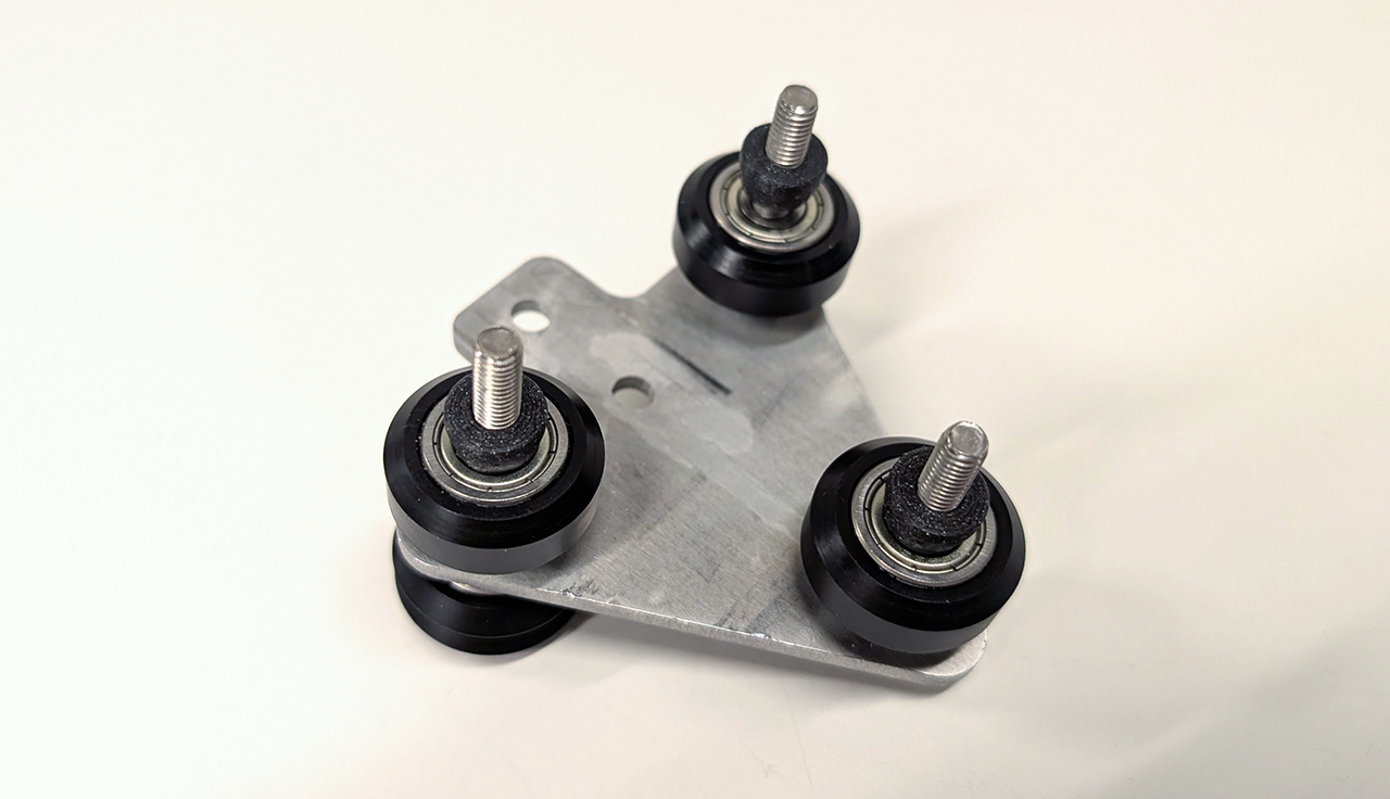
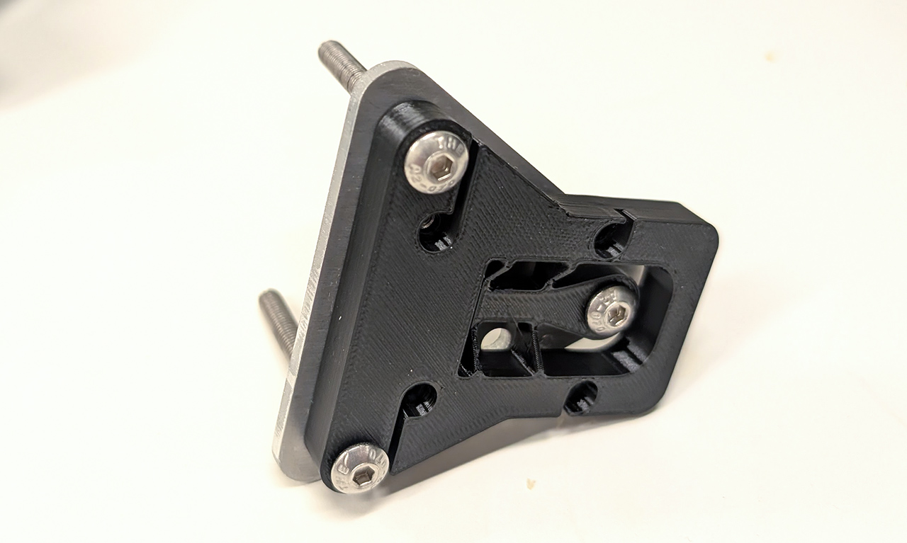
Here are the parts you'll need to assemble one of the two carriages supporting the gantry:

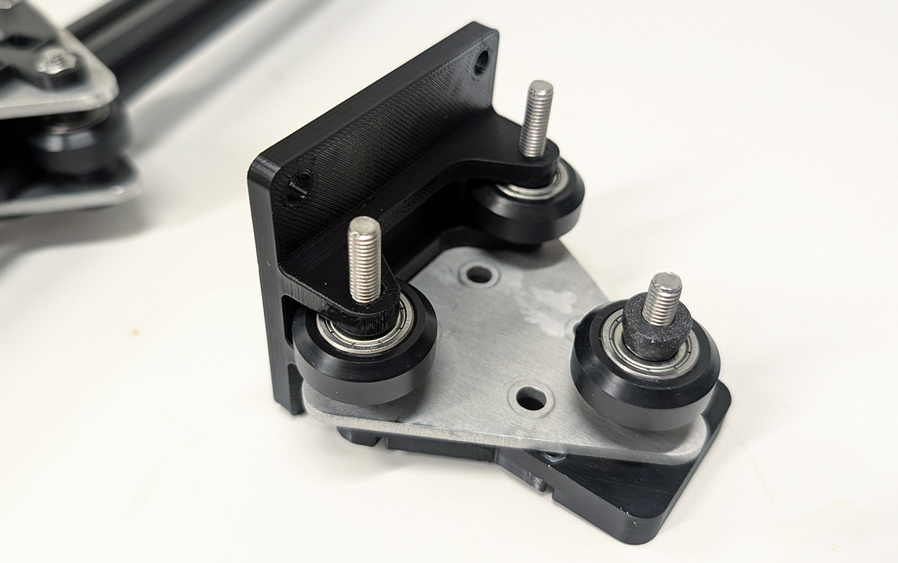
On the top of the carriage, place the V-wheels and the flexure:
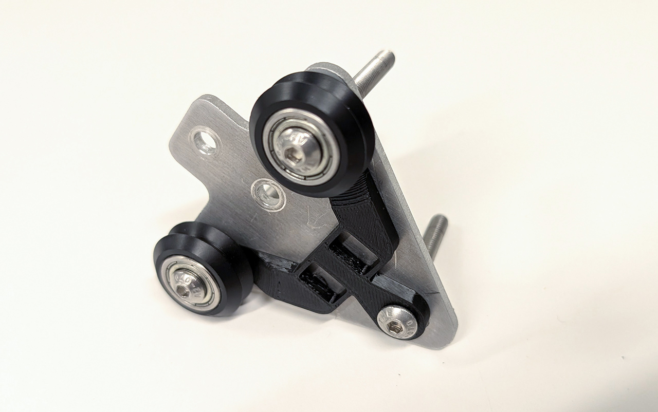
In between the two plates, come the three wheels, with spacers on both sides:
After adding the bottom plate, finish off with the bottom flexure. This one is designed to hold the nuts in place:

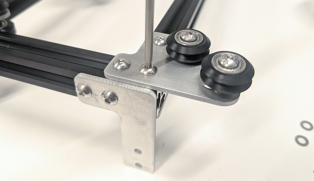
Tighten the screws holding the two V-wheels. Start tightening the third screw, but do not tighten it all the way:

After sliding the carriage onto an extrusion, the flexure should help tensioning the carriage to just the right amount. If that is not the case, your extrusion might have a different pitch, and you'll need to print a different flexure. If the motion seems smooth while pressing onto the extrusion the right amount, tighten the last screw to finish off:

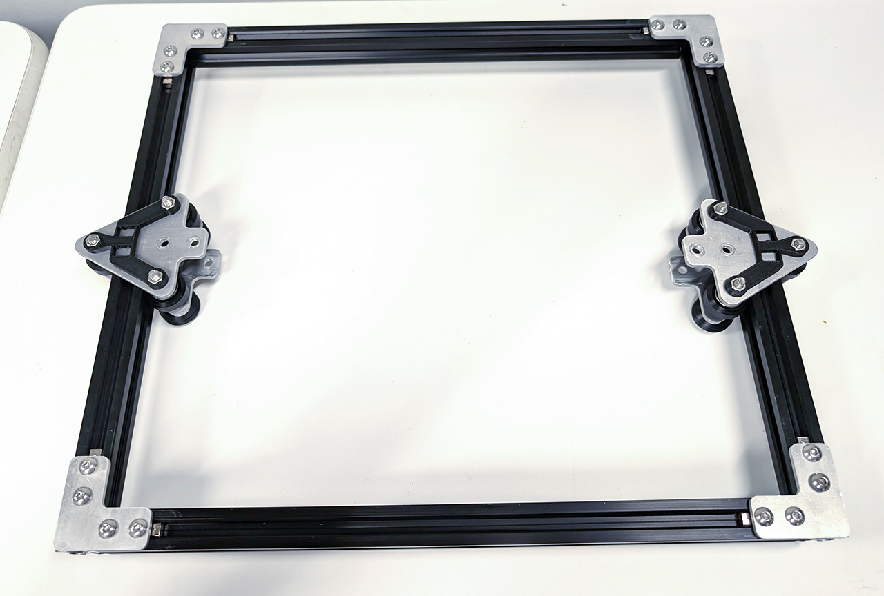
After repeating those operations for a second carriage, build the frame with four brackets on the bottom side:
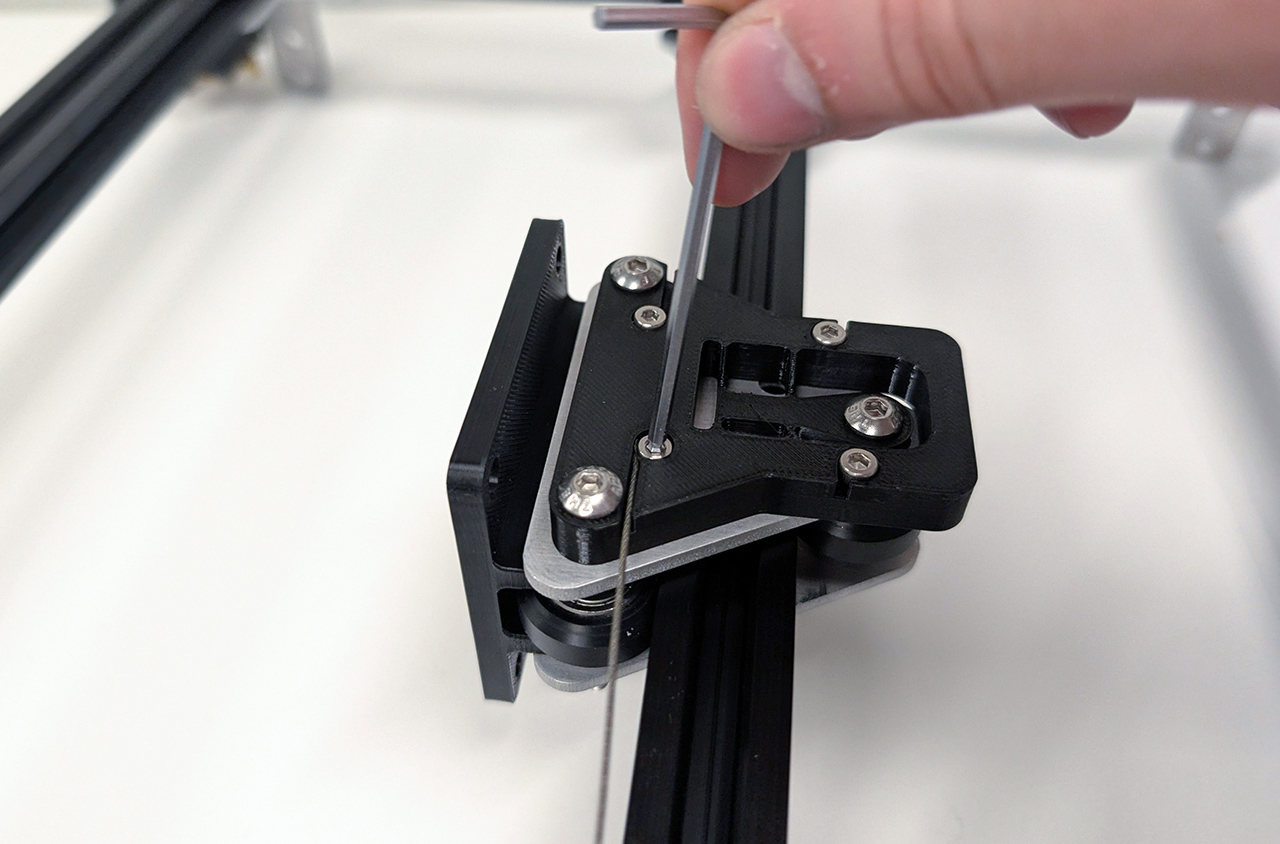
You can now assemble the toolhead's carriage. The construction is similar, but starts with inserting M3 nuts on the bottom side of the top flexure part. This part is more complex, as it is also used to terminate the cable.

Place the flexure on the top plate, and insert the M5 screws:
Add the wheels and the front plate, which also serves as spacers for the two wheels in the front.
Finish off with the bottom flexure:

As before, tighten the two front screws only, and keep the third one pretty loose:

After sliding the carriage onto the gantry's extrusion, tighten the third screw. You might need to insert the extrusion at an angle.

Secure the top plates using screws and T-nuts:

On the bottom side, insert printed spacers and secure evering with more screws.

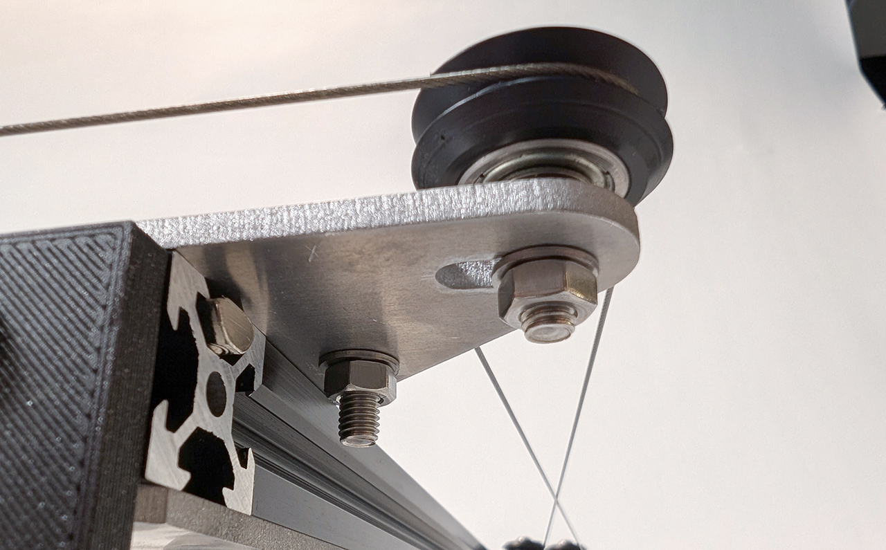
Add the corner holding the pulleys on the top left and right corners.
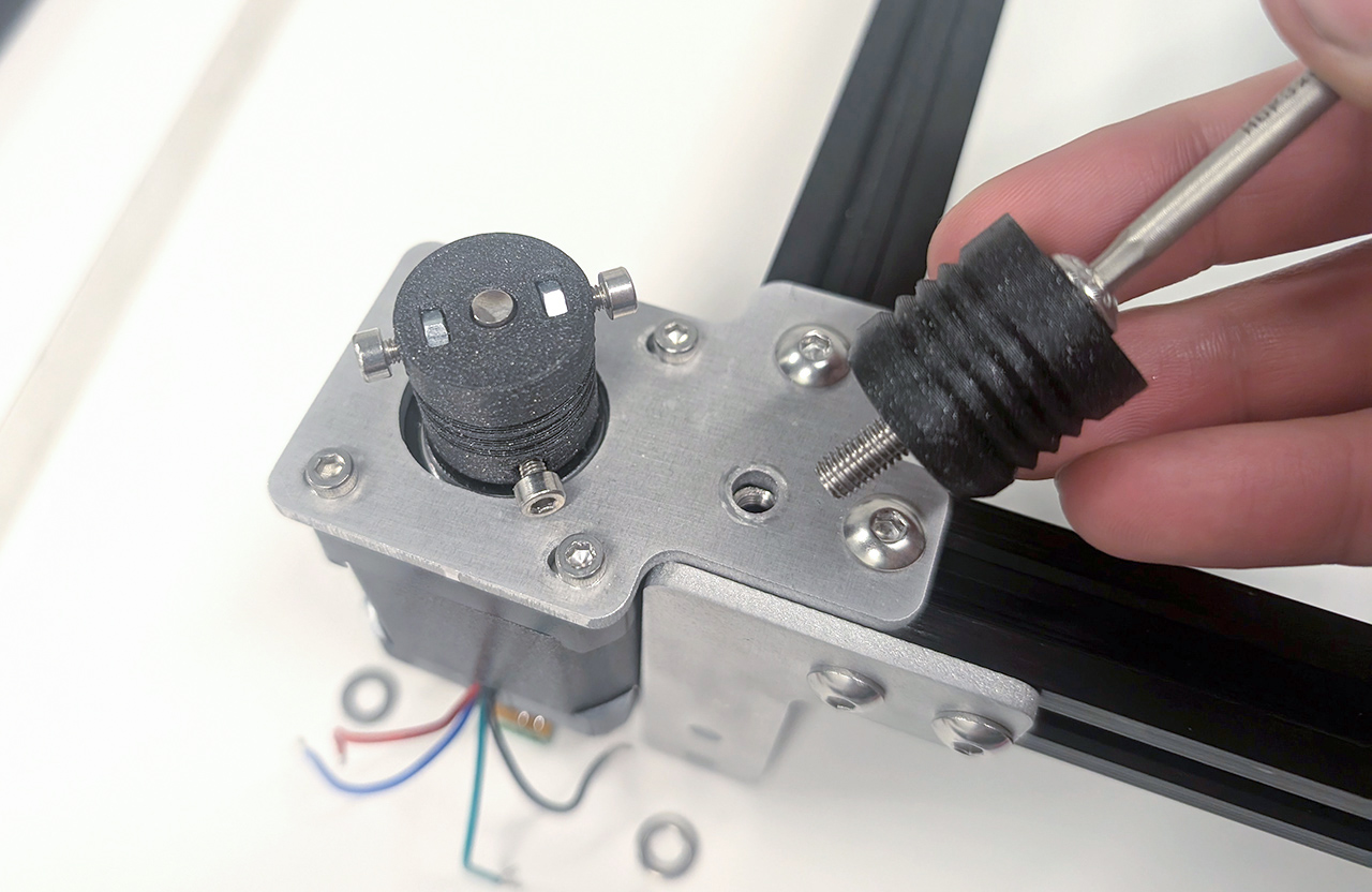
Secure the motors to their respective plates, and the capstan onto it. You'll need to insert M3 nuts in the slots, then fasten the screws while keeping it well-centered.

Assemble the motor's corner pieces on the main frame, and add the capstan pulleys. Note that there are two bearings that need to be inserted in these, as well as a spacer in between to avoid putting compression force on the two bearings.
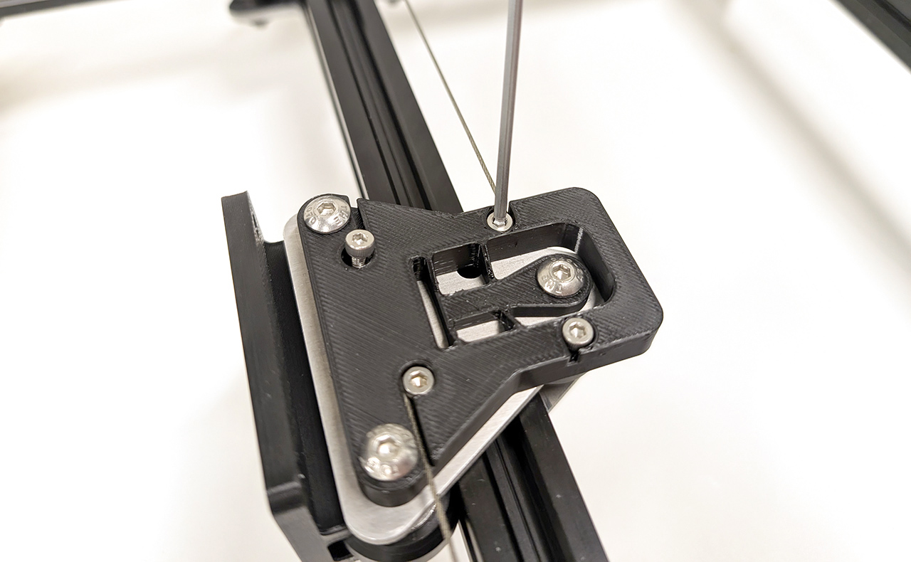
Start routing the cable by tightening and M3 screw on the carriage and inserting the cable's end under the screw.
Route the cable to the pulley, then to the capstan assembly. Make the cable circulate around the two capstans, from the bottom to the top groove.
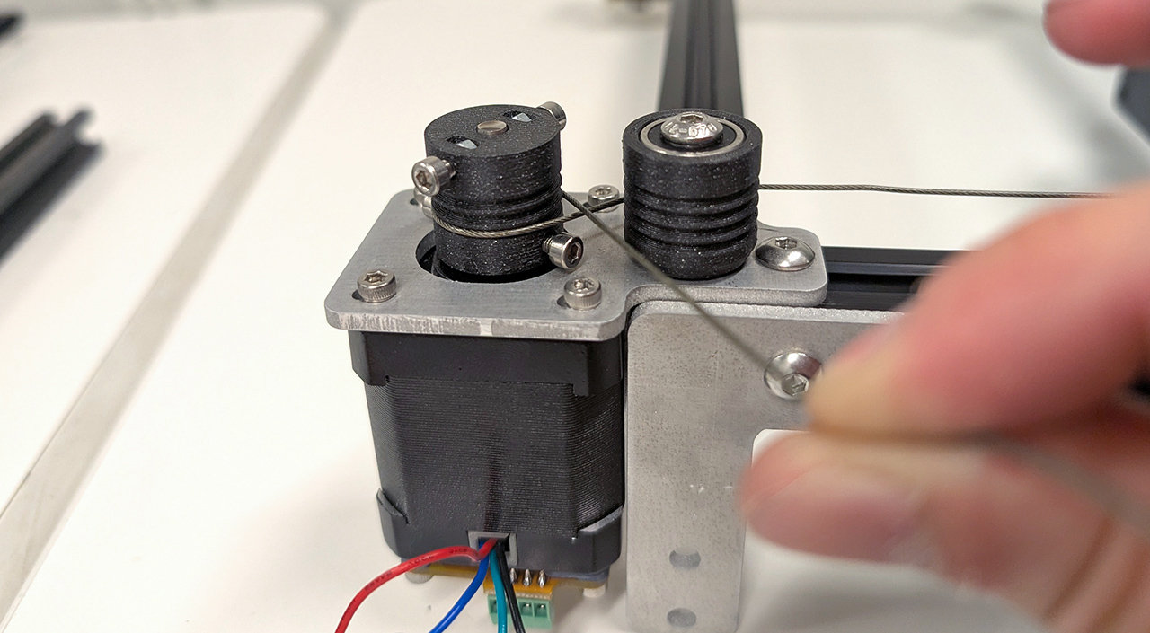
Here is capstan assembly, with the cable in place:

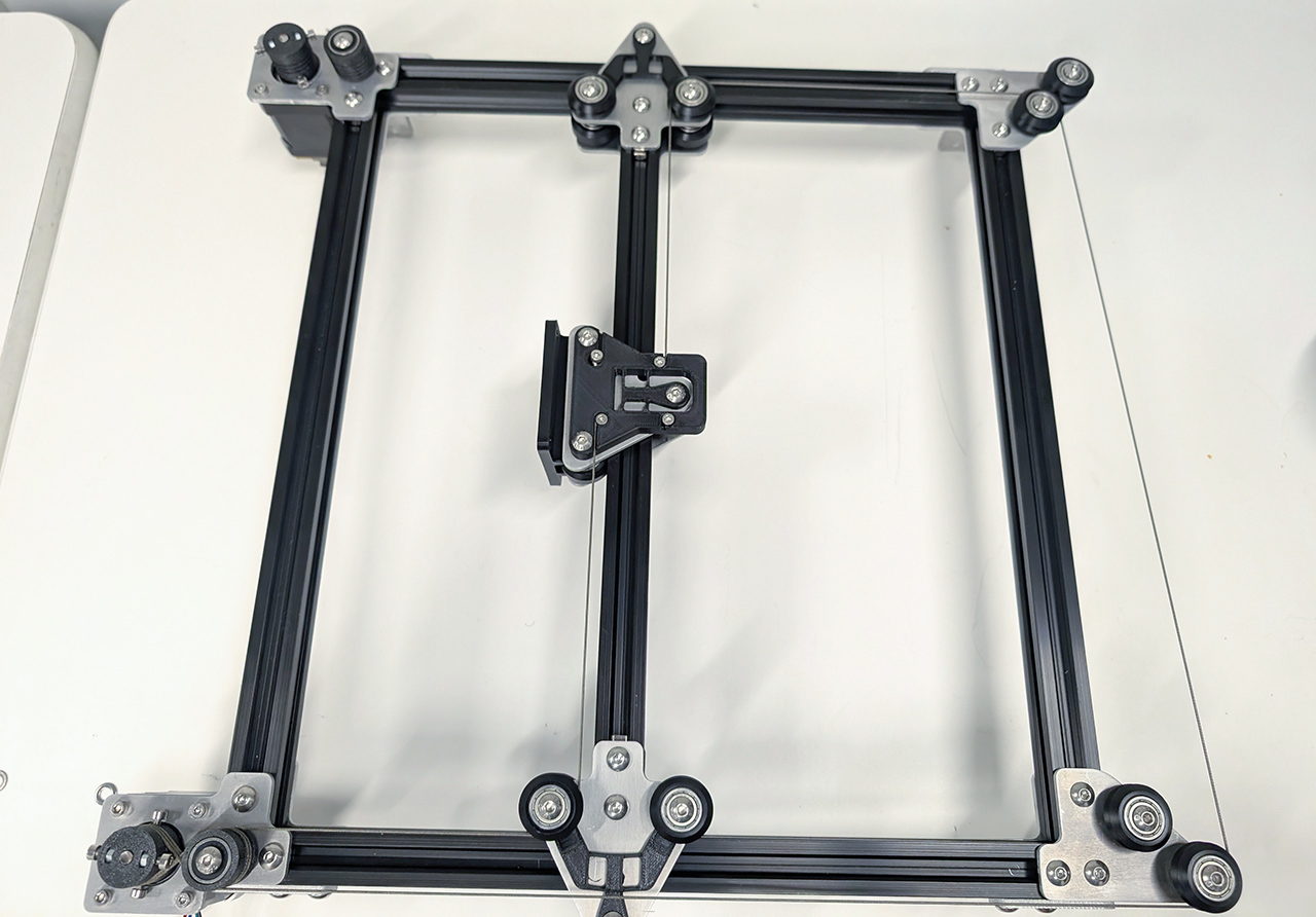
Guide the cable to the pulley on the back side of the machine.

Here is the complete path taken by the cable:
Tighten the end of the cable to finish off this loop:
Add tension to the loop by sliding the pulley and tightening the screw holding it:
Repeat the same operations for the other loop to complete the machine. Congratulations, you should have a nicely tensioned coreXY motion system. You can optionally add the feet, or you can mount it on your favorite extrusion assembly.
Demo
Download
The files to 3D print can be found here.
The files to laser cut or waterjet can be found here.